Contact Us For Pricing:
(954) 306-3180 | info@winecellarinternational.com

High Static Wine Cellar Cooling Series
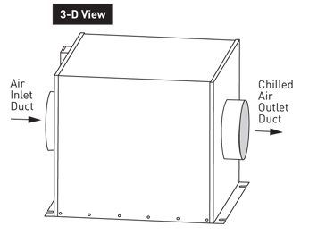
The High Static (HS) Systems are designed to provide refrigerated air to medium-high temperature spaces. HS evaporators are powerful enough to be installed as far as 25 feet away from the refrigerated room. The chilled air is ducted back into the room, eliminating noise or the inconvenience of an in-room evaporator, which frees up valuable space.
Hs evaporators are available in capacities from 1,800 to 20,000 BTU per hour and are used with an R134a refrigerant.
Available Option
- Secondary drain pan for elevated and sensitive installations
- Stainless steel cabinets for high corrosive environments
- Eco-friendly water-cooled condensing units available
- Industrial applications available
- Air defrosting coil requires does not require an additional heater
- Fan blades engineer for very low-noise
- Staggered high performance coils with copper tubing expanded mechanically into aluminum fins
- Housing constructed with insulated rust-proof aluminum
- Permanently lubricated motor fully thermally protected
- Automatic expansion valve(standard) ensures constant coil temperature to promote “Humidity Balance”
- Pump-down solenoid valve(standard) protects compressor in the event of leaks
- Expansion valve and liquid line solenoid valve standard
- Air handlers are designed for a maximu of 50′ total duct at 1″ static pressure
- Suction line accumulators recommended
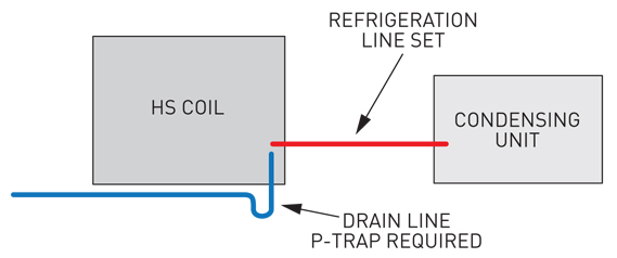
- Drain must have a vented P-trap
- Connections at coil do not indicate refrigeration line size


Field Wiring
L1 115V Line Voltage
N Neutral
SV Solenoid Valve
FM Fan Motor
TP Temperature Probe
Back of Controller Connections
10 Temperature Probe
11 Temperature Probe
4 Neutral
5 115V Line Voltage
2 Jumper from 5
3 Switch Leg to Fan Coil
C NO Internal normally open contact
Fan Coil Wiring

Condensing Unit Wiring

- Installation diagram shows the typical duct layout. Actual layout to be determined by installer.
- Duct work not to exceed 50′ total length.
- For short duct length mat install a fan speed to slow down fan speed. Keep line sets as short as possible.
- The system is controlled by a pump down control system. There is no control wiring between thermostat and condensing unit.
- Standard line sets should be 50′ or less. Extended runs may require larger line sizes and 3oz. oil must be added for every 10′ over 35′. Drain line must always flow downhill to drain or pump.
- The line connections at Fan Coil and Condensing Unit may not be the same as the required line sizes.
- Excessive number of turns will cause refrigerant flow problems. This could cause early compressor failure. Suction line accumulators are recommended. Required if working lower than the normal 55-65° operating range from wine cellar.